
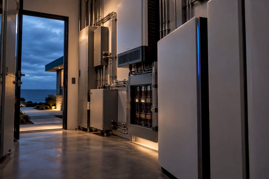
Grid-forming inverters create and hold an internal voltage phasor, acting as a voltage source. Grid-following inverters synchronize to an existing voltage reference through a phase-locked loop and regulate current, acting as a current source. The practical trade-off: specify grid-forming where system strength is low, black-start or islanding matters, or inverter-based resource share is high; specify grid-following where the grid is stiff and ride-through requirements under IEEE 1547/2800 are already met. Either way, the decision belongs in an EMT study, not a spec sheet assumption.
TL;DR:
- Grid-forming inverters are essential for low-system strength, black-start capability, or high inverter share, while grid-following inverters suit stable, strong grids.
- Grid-forming controls provide immediate voltage and frequency stability during disturbances, offering faster synthetic inertia compared to grid-following systems.
- Fault-current contributions from grid-forming inverters can reach nearly double rated current briefly, unlike the limited 1.1 to 1.2 times rated current of grid-following units.
- Proper sizing, testing, and EMT studies are critical before selecting or retrofitting inverter-based resources to ensure stability and protection coordination.
- Industry standards are evolving, with UNIFI and ESIG working toward interoperability and improved GFM-specific performance requirements.
Table of Contents
- Grid-Forming Technology: Control Principles and Hardware Limits
- Grid-Following Systems: PLLs, Current Loops, and Their Limits
- Grid Forming vs Grid Following: A Side-by-Side Comparison
- What Studies Should You Run Before Choosing GFM or GFL?
- How Do You Validate GFM Performance Before Deployment?
- UNIFI, IEEE, and NERC: Where the Standards Stand Today
- How Did Grid-Forming and Grid-Following Technology Develop?
- Why Grid-Forming Capacity Matters for Renewable Integration
- Real-World Performance: How GFM and GFL Behave Under Stress
- Prime Microgrid's Take: Why Headroom Beats Optimism
- Where Grid-Forming Fits in a Prime Microgrid Design
- Where to Go Deeper on Grid-Forming Standards
- Sources
- FAQ
Grid-Forming Technology: Control Principles and Hardware Limits
A grid-forming (GFM) inverter's control objective is to hold an internal voltage magnitude and phase angle steady through the transient timeframe, the way a synchronous generator's rotor holds a reference through inertia. It doesn't wait for a signal to lock onto. It creates one, and the rest of the grid locks onto it.
Three control strategies dominate current GFM designs. Droop control mimics generator governor response, adjusting frequency and voltage output based on active and reactive power deviations. Virtual synchronous machine (VSM) control goes further, embedding a mathematical model of rotor inertia and damping directly into the converter's control loop. Virtual oscillator control takes a different mathematical path, using coupled nonlinear oscillators to reach synchronization without explicitly modeling a machine. Each converges on the same functional outcome: a stable local voltage reference that other devices on the circuit can follow.

This is where synthetic inertia comes from. Because the GFM controller reacts within milliseconds rather than the seconds a governor takes to respond, it can arrest frequency decline immediately after a disturbance, a role synchronous generators once handled through physical rotating mass.
Hardware sets the ceiling on that behavior. Because GFM inverters hold voltage regardless of load, a fault or an inrush event drives current up until:
- Semiconductor overcurrent limits force the controller into a temporary current-limiting mode
- Thermal limits on IGBTs or SiC devices cap how long that elevated current can be sustained
- Protection logic must coordinate around a fault response that looks nothing like a synchronous generator's
Grid-Following Systems: PLLs, Current Loops, and Their Limits
A grid-following (GFL) inverter assumes the grid already has a stable voltage and frequency reference, then measures it continuously through a phase-locked loop (PLL). The PLL tracks the grid's phase angle in real time, and the inverter's current-control loop injects power in phase with that measured reference.
In the sub-transient timeframe, this makes a GFL inverter behave essentially as a constant-current source. It doesn't try to hold voltage. It tries to match whatever voltage and frequency the grid already presents, then push a commanded amount of current into it. That distinction, current-source versus voltage-source, is the single fact that explains almost every downstream difference between the two technologies, a point confirmed in modeling work comparing droop-based grid-following and grid-forming control architectures.
GFL's advantages are practical ones. The control architecture is simpler, better understood by protection engineers, and well suited to large, utility-scale plants tied into a grid with abundant synchronous generation nearby.
Its weaknesses show up at the edges:
- PLL tracking can become unstable or oscillatory on very weak grids, where the "reference" it's chasing is itself soft and easily perturbed
- A GFL inverter has no mechanism to black-start a de-energized system, since it has nothing to synchronize to
- Fault response is limited by design, since the current-control loop is not built to source large transient current the way a voltage source naturally does
Grid Forming vs Grid Following: A Side-by-Side Comparison
The cleanest way to see the difference is to line up what each control architecture actually does under stress, not just at steady state.
| Characteristic | Grid-Forming (GFM) | Grid-Following (GFL) |
|---|---|---|
| Primary reference | Voltage source (sets phasor) | Current source (tracks reference) |
| Transient role | Sets frequency and voltage instantly | Follows existing frequency and voltage |
| Black-start capability | Yes, with adequate headroom and energy buffer | No |
| Synthetic inertia | Yes, fast response via control loop | Limited to none |
| Typical fault-current contribution | Up to around double rated for a limited duration | Roughly 1.1 to 1.2x rated |
| Dependence on system strength (SCR) | Performs well in weak grids | Needs a reasonably strong grid to stay stable |
| Retrofit feasibility on existing plants | Often requires new firmware or hardware | Usually native to existing installed base |
That fault-current gap deserves a physical explanation, because it drives protection coordination decisions. A GFM inverter holds voltage, so when a fault drops line impedance, the current it delivers follows Ohm's law directly: I equal delta V divided by Z. On a strong grid with very low impedance, that same equation works against the inverter. The voltage the converter is trying to hold barely needs to move to demand enormous current, and the hardware clips it well before the "ideal" voltage-source response would suggest. This is why some GFM units cap fault contribution near 2x rated for only a few cycles rather than sustaining it indefinitely.
Statistic to flag for protection engineers: test literature documents GFL fault contributions of roughly 1.1 to 1.2 times rated current, while certain GFM designs can push toward 2x rated current, but only briefly. Relay settings tuned around synchronous-generator fault behavior, often 5 to 10 times rated current, will not see either inverter type the same way, and that mismatch is a common source of nuisance trips or missed protection during commissioning.

Retrofit feasibility often gets underweighted in early design conversations. Many installed GFL fleets can be upgraded toward GFM behavior through firmware changes alone, but only if the underlying power electronics have the thermal and overcurrent margin to support voltage-source behavior. Without that headroom, the software update is available, but the hardware simply can't use it safely.
What Studies Should You Run Before Choosing GFM or GFL?
Skipping straight to a hardware order based on a rule of thumb is how weak-grid instability problems end up discovered in the field instead of on a test bench. Work through this sequence instead:
- Estimate short circuit ratio (SCR) at the point of interconnection. Low SCR, generally below 3, is the strongest early signal that grid-following alone will struggle. Treat SCR as a screening tool, not gospel. Cluster-level interactions and vendor tuning can shift the real threshold in either direction, according to modeling work at UT Austin.
- Scope an EMT (electromagnetic transient) study covering fault ride-through, phase jumps, and reclosing events specific to the interconnection.
- Confirm black-start and islanding requirements with the facility owner or utility before assuming grid-following is adequate.
- Inventory motors, transformers, and other inrush-heavy loads on the intended cranking path; each one competes for the same limited overcurrent headroom.
- Quantify acceptable fault-current headroom and thermal margin in writing, not as a vendor assumption.
- Require validated EMT models and a PHIL test plan from any GFM vendor before specification lock.
Do not default to mandating GFM everywhere. Industry guidance increasingly cautions that over-specifying grid-forming capability on a strong, well-interconnected system adds cost and complexity without a corresponding stability benefit; the right call depends on characterizing the specific system first, not applying a blanket rule.
Pro Tip: Put fault-current headroom and thermal margin numbers directly into the interconnection agreement, not just the equipment spec sheet. Vendors will size to whatever number is contractually binding, and a soft requirement gets soft compliance.
How Do You Validate GFM Performance Before Deployment?
Steady-state analysis cannot tell you whether a grid-forming inverter will behave correctly during a fault, a phase jump, or a black-start sequence. Only time-domain testing shows that, which is why ESIG's testing guidance treats EMT and hardware-in-the-loop (HIL) validation as mandatory, not optional, for GFM verification.
Test plans should reproduce, at minimum:
- Weak-grid connection scenarios with SCR values near the project's actual worst case
- Sudden phase-angle jumps, which stress the control loop's transient response directly
- Fault insertion and clearing, checked against the fault-current numbers in your protection settings
- A full black-start sequence, including sequential load pickup
- Breaker reclosing events, which can trigger control interactions steady-state models miss entirely
Vendor-supplied EMT models need validation against physical hardware, not blind acceptance. Programs run by NREL and Sandia using PHIL testbeds show this is a practical, repeatable process, not a research-lab luxury.
Pro Tip: Ask for reclosing test results specifically. It's the scenario commissioning teams forget most often, and the one most likely to expose timing errors between protection relays and inverter controls.
UNIFI, IEEE, and NERC: Where the Standards Stand Today
The standards landscape for grid-forming technology is still catching up to the hardware. The UNIFI Consortium is building vendor-agnostic functional specifications covering AC-side performance across battery, PV, wind, and hydrogen-based GFM units, aiming for the kind of interoperability that lets a utility swap vendors without rewriting its interconnection studies.
IEEE 1547 and IEEE 2800 currently define interconnection and ride-through requirements largely built around grid-following behavior. Both are evolving to address GFM-specific performance, but gaps remain in areas like transient voltage support and fault-current characterization.
NERC guidance leans toward system-specific characterization before mandating GFM broadly. When you're drafting procurement language, request:
- ICD (interface control document) files describing the inverter's control behavior
- Validated EMT models, not vendor-claimed performance curves
- Documented conformance to UNIFI's functional specifications where applicable
- Independent test reports, not internal vendor summaries alone
How Did Grid-Forming and Grid-Following Technology Develop?
Grid-following control came first because it matched the grid it was born into. Early inverter-based generation, mostly rooftop solar and small wind, connected to grids still dominated by synchronous generators. Those generators supplied all the inertia and voltage stability the system needed. Inverters just had to inject current in step with an already-strong reference, and PLL-based synchronization did that job well enough for decades.
The math changed as inverter-based resources grew from a marginal share of generation to a majority in some regions. Synchronous generators were retiring or running at lower output, and the "strong reference" that grid-following inverters depended on started to weaken in specific locations, particularly at the ends of long transmission lines or on island-like grids with few remaining rotating machines.
Grid-forming control emerged from that gap, drawing directly on decades of synchronous machine theory. Virtual synchronous machine control, one of the earliest GFM approaches, explicitly modeled generator inertia and damping inside a converter's control software, essentially teaching an inverter to behave like the rotating equipment it was displacing.
Utility-scale deployment is recent. Large-scale GFM projects, island grids, and a handful of transmission-connected battery installations have only become commercially significant in the past several years, driven partly by grid operators in low-inertia regions demanding it. The UNIFI Consortium's formation reflects that shift: an industry-wide recognition that ad hoc, vendor-specific GFM implementations wouldn't scale without a shared functional specification.
Why Grid-Forming Capacity Matters for Renewable Integration
As synchronous generation retires and inverter-based resources take a larger share of total capacity, the grid loses the physical inertia that once absorbed disturbances automatically. Frequency excursions that used to be barely noticeable can become destabilizing on a system with too few spinning machines and too many current-following inverters that have nothing to hold the reference steady.
Simulation studies replacing synchronous generators with grid-following-only inverter fleets show measurably worse rate-of-change-of-frequency (RoCoF) and deeper frequency nadirs after a disturbance, compared with systems that retain some inertia-emulating grid-forming capacity, according to comparative modeling published in Energies. That is not a marginal difference. It is the difference between a frequency dip that protection systems ride through and one that trips load or generation offline.
This matters directly for large-scale renewable integration. Wind and solar plants, by nature, replace synchronous capacity rather than adding to it, which means every gigawatt of new inverter-based generation without grid-forming capability is a gigawatt that adds no inertia back to the system. Grid operators managing high renewable penetration increasingly treat GFM capacity as a resilience asset in its own right rather than just a generation source. A system with a meaningful share of grid-forming inverters recovers from disturbances faster and tolerates a higher share of inverter-based resources overall, which is precisely why interconnection studies for large renewable projects increasingly ask GFM-specific questions that didn't exist a decade ago.
Real-World Performance: How GFM and GFL Behave Under Stress
Laboratory and field data back up what the control theory predicts, and the clearest signal comes from frequency response testing. Simulation work modeling IEEE benchmark systems found that swapping synchronous generators for grid-following-only inverter capacity worsened both RoCoF and frequency nadir after a disturbance, while systems retaining grid-forming inertia emulation held frequency closer to nominal through the same event, per the Energies comparison study.
Fault behavior tells a parallel story. Grid-following units tested under fault conditions consistently topped out near 1.1 to 1.2 times rated current, essentially incapable of the transient overcurrent a synchronous generator would naturally supply. Grid-forming units in the same test literature reached closer to double their rated current for a few cycles before hardware limits forced current clipping, a documented pattern in inverter fault-current research.
Weak-grid connection scenarios reveal the PLL's limits most clearly. Grid-following inverters connected to low-SCR test circuits showed tracking instability and oscillatory behavior that didn't appear on stronger test circuits with the same hardware. Grid-forming units, holding their own voltage reference rather than chasing one, stayed stable through the same weak-grid conditions.
None of these results argue for one technology everywhere. They argue for matching the technology to the measured strength of the specific interconnection point, verified through EMT testing rather than assumed from a generic SCR rule of thumb.
Prime Microgrid's Take: Why Headroom Beats Optimism
Every grid-forming versus grid-following debate eventually turns into a hardware-sizing conversation, whether the spec sheet admits it or not. We've found the projects that run into trouble are rarely the ones with the wrong control architecture. They're the ones where the right architecture got specified without the overcurrent and thermal margin to actually deliver on it.
Our approach leans on staged commissioning and deliberately conservative headroom, because a grid-forming inverter that looks perfect in a datasheet still needs to prove it in an EMT study and, ideally, a hardware-in-the-loop test before it carries a black-start responsibility. For estate and property-scale microgrid design, that means sizing for the worst realistic inrush event, not the average one.
If you're scoping a project where grid strength or islanding needs are in question, we're glad to walk through what a technical site review looks like.
— Prime Microgrid
Where Grid-Forming Fits in a Prime Microgrid Design
If you're weighing grid-forming against grid-following for an estate, farm, or commercial property, the honest answer is that most resilience-focused microgrids end up using both. Prime Microgrid's Estate Microgrid Systems, Battery Retrofit Systems, and Hybrid Generator Systems are engineered around the property's actual electrical demand, which means the inverter headroom, black-start capacity, and staging sequence get sized to your site's real inrush profile rather than a generic assumption.

A technical scoping call with our team typically covers an EMT-informed review of your site's electrical characteristics, a walkthrough of existing wiring and transformer loads, and a black-start feasibility check if islanding is part of your resilience goals. Instead of a packaged system sold off a shelf, you get a system designed around what your property actually needs to ride through a grid event. If a private, engineer-reviewed system design sounds like the right next step, reach out through Prime Microgrid's design and commissioning services to schedule a site review.
Where to Go Deeper on Grid-Forming Standards
Start with UNIFI's functional specifications for the interoperability framework vendors are building toward. Read ESIG's GFM performance testing report for the case behind EMT and hardware validation. The DOE's specifications document and NREL's PHIL testbed research round out the technical baseline any project team should review before finalizing a spec.
Sources
- Universal Interoperability for Grid-Forming Inverters (UNIFI) — WisPo ECE
- ESIG — GFM performance testing report (2025)
- Specifications for Grid-Forming IBRs — U.S. DOE (UNIFI-related)
- WES article on inverter fault current (2025)
FAQ
What Is Grid-Forming, Exactly?
Grid-forming is an inverter control strategy that creates and holds its own internal voltage and frequency reference, acting as a voltage source. This lets it support black-start, islanding, and fast frequency response, functions DOE documentation confirms a grid-following inverter cannot perform on its own.
What Companies Make Grid-Forming Inverters?
Multiple inverter manufacturers across the battery, solar, and hydrogen sectors are developing grid-forming capable products, and the UNIFI Consortium is working to standardize functional requirements across vendors. Prime Microgrid designs and specifies systems using grid-forming capable equipment as part of custom estate microgrid projects rather than manufacturing inverters itself.
What Is a Grid-Following Inverter?
A grid-following inverter synchronizes to an existing grid voltage using a phase-locked loop, then injects current in phase with that reference. It behaves as a current source and cannot establish its own voltage reference, which means it has no black-start capability on its own.
What Are Grid-Forming Solar Inverters and How Do They Work?
Grid-forming solar inverters apply voltage-source control, such as droop or virtual synchronous machine algorithms, to solar generation equipment so it can set frequency and voltage rather than just following the grid. They provide synthetic inertia and fault-current support, but only within the thermal and overcurrent limits of the underlying power electronics.
How Do I Decide Between Grid-Forming and Grid-Following for My Project?
Start with a short circuit ratio estimate at your interconnection point and confirm whether black-start or islanding is required. If the grid is weak, inverter-based resource share is high, or islanding matters, plan for grid-forming capability backed by an EMT study; a strong, well-interconnected grid may not need it.